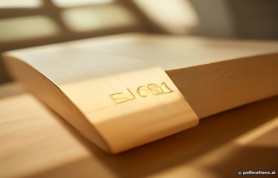
For 1.0–2.5mm laminated grayboard, set V-groove scoring depth to 55–65% of measured board caliper (e.g., 0.55–0.70mm on 1.2mm board) with blade tip depth tolerance of ±0.10mm to achieve clean, fiber-controlled 90-degree corners without cracking or through-cuts. Verify setup under ISO 186:2020 conditioning (23°C ± 1°C, 50% ± 2% RH) and release the lot only when groove registration holds within ±0.15mm across the full die sheet.
Luxury rigid packaging demand in 2026 continues to shift toward sharper corner geometry — magnet-close rigid boxes, hinged lid-and-base sets, and book-style collector packaging all depend on knife-crisp 90-degree folds that wrapping gluing lines can run at speed. This guide anchors that trend where it belongs: in the physics of the V-grooving operation itself, and in the tolerances your procurement team should write into every rigid box specification. All numerical worked examples below are hypothetical engineering scenarios for illustration; validate against your own board lots and machine trials.
1. V-Grooving Mechanics: Why Depth Controls Corner Quality
V-grooving (also called V-cutting or notching) removes a triangular section of grayboard along the fold line, leaving a thin live hinge of board material. When the board folds, the remaining web acts as a controlled fiber hinge; the geometry of the removed wedge — included angle (typically 80°–120°), depth, and residual web thickness — determines whether the folded corner is crisp, rounded, cracked, or broken through.
The governing engineering relationship for a hypothetical worked example: on 1.2mm laminated grayboard with a 90° included V-angle, a scoring depth of 0.65mm (54% of caliper) leaves roughly 0.55mm of residual material at the groove shoulders and a hinge web of ~0.15–0.20mm at the apex — sufficient for a full 90° fold with less than 2° spring-back on a well-calibrated machine. Cut deeper than ~70% of caliper and the apex web collapses or tears; cut shallower than ~50% and fold radius grows past 1.5mm, producing the soft, clouded corner that fails luxury brand aesthetic QC.
Q: If our grayboard caliper measures 1.2mm on the spec sheet, why does 0.72mm (60%) depth work on one machine and crack on another?
A (direct): Because the effective scoring depth is measured from the actual board surface, not the nominal spec — caliper variation on laminated grayboard commonly runs ±0.05–0.10mm per ISO 534 measurement. Mechanical reason: a 0.10mm over-measurement of board thickness means the blade penetrates proportionally deeper into the remaining web, so a nominal 60% setting can become an effective 67% cut at the thin spot, shearing the hinge. Procurement recommendation: specify grayboard to a caliper tolerance band of ±0.05mm per lot, require mill certificates with TAPPI T411 caliper data, and mandate first-article depth verification on every new board lot before production release.
2. Scoring Depth Tolerance Table by Board Grade
The following reference matrix consolidates standard V-groove setups for common rigid box board constructions. Treat values as starting points for machine trials, not universal constants — fiber orientation, lamination adhesive solids, and blade wear all shift optimal depth by 3–8%.
| Board Construction | Nominal Caliper | Scoring Depth (% caliper) | V-Angle | Target RWT | Governing Standard / Test Protocol |
|---|---|---|---|---|---|
| Laminated grayboard (wrapped rigid box) | 1.0mm | 0.55–0.65mm (55–65%) | 90°–100° | 0.15–0.20mm | ISO 534 / TAPPI T411 caliper |
| Laminated grayboard, hinge lids | 1.5mm | 0.82–0.98mm (55–65%) | 90° | 0.20–0.25mm | ISO 3039 processed board thickness |
| Heavy-duty base board | 2.0–2.5mm | 1.15–1.55mm (55–62%) | 100°–120° | 0.25–0.35mm | ASTM D645 / ISO 3039 |
| Wrapped panel fold integrity (post-wrap) | — | — | — | Wrap adhesive coverage ≥90% | ASTM D903 peel / ISO 186:2020 conditioning |
| Transit validation of finished rigid box | — | — | — | No corner fracture after ISTA 3A drop sequence | ISTA 3A / ASTM D4169 DC-13 |
Board conditioning matters as much as depth. In strict accordance with ISO 186:2020 and ASTM D685 conditioning specifications (23°C ± 1°C, 50% ± 2% RH), grayboard should equilibrate for a minimum of 24 hours before grooving. A board entering the machine at 9% moisture content versus the 7–8% equilibrium target will exhibit higher hinge brittleness and a measurably higher corner-crack rate, particularly on recycled-content board above 90% OCI.
3. Four-Step Machine Setup SOP for Crisp 90° Corners
Step 1 — Verify board caliper and conditioning. Measure actual caliper at 10 positions across the sheet with a dead-weight or digital caliper (e.g., Mitutoyo-type instrument, resolution 0.001mm); accept the lot only within ±0.05mm of specification and only after ISO 186:2020 conditioning. Record the measured mean — this value, not the spec-sheet number, drives depth calculation.
Step 2 — Set scoring depth and blade geometry. Program depth at 55–65% of the measured mean caliper; set blade projection with a depth gauge to ±0.10mm tolerance and confirm knife edge condition (replace blades showing >0.02mm edge wear or any visible chipping). Confirm V-angle matches the dieline specification — a 90° groove paired with a 120°-angle blade produces instant hinge failure.
Step 3 — Verify registration and groove alignment. Run a 3-sheet setup batch and check groove centerline against dieline fold lines on a calibrated inspection table; registration tolerance is ±0.15mm, and groove-to-groove pitch on multi-groove panels must hold within ±0.20mm cumulative. Off-center grooves shift the fold axis, creating exposed gray edge and corner miswrap.
Step 4 — First-article fold test and lot release. Fold 10 specimens to 90° by hand (simulating wrap-line handling) and inspect: accept if the hinge shows no fiber fracture, spring-back ≤2°, and corner radius ≤0.8mm. A practical illustrative lab record format: specimens conditioned at 23°C ± 1°C, 50% RH per ASTM D685; caliper verified on a 0.001mm-resolution digital caliper; 10-specimen statistical average with tolerance ±0.15mm. Always label such records as your own internal trial data rather than generic benchmarks.
4. Defect Diagnostics: Troubleshooting Matrix
| Defect | Root Cause | Corrective Action | Verification Standard |
|---|---|---|---|
| Hinge cracking at 90° fold | Depth >65% of caliper; board moisture <7%; dull blade tearing fibers | Reduce depth 3–5%; recondition board 24h; replace blade | ISO 186:2020 conditioning; fold visual QC |
| Corner spring-back >3° / rounded corners | RWT >0.35mm (underscored groove); V-angle too obtuse | Increase depth toward 60–65%; correct blade angle to dieline spec | Angle gauge check; ISO 3039 thickness verification |
| Adhesive debonding at fold after ocean transit | Container sweat driving board MC >12%; cold-set adhesive shear loss | Specify higher-solids lamination adhesive; add desiccant and moisture-barrier wrap in master cartons | Cobb 60 absorption ≤35 g/m²; ASTM D903 peel retention |
| Exposed gray edge / miswrap at corner | Groove registration off-center >±0.15mm | Re-zero sheet feed guides; verify pitch on inspection table | ±0.15mm registration SOP check |
The debonding row deserves emphasis for US-bound shipments: 30-day trans-Pacific ocean freight routinely exposes rigid boxes to 85%+ RH cycling inside containers. Where Cobb 60 water absorption exceeds 35 g/m² on the wrap stock or the grayboard substrate, transit delamination risk rises sharply — require Cobb data on material certificates, and consider ISTA 3A or ASTM D4169 Distribution Cycle 13 validation including atmospheric preconditioning for any new rigid box program.
5. Procurement Specification Language & Logistics Derating
Write grooving requirements into your PO as measurable, testable language: (1) board caliper ±0.05mm per lot with TAPPI T411 certificate; (2) scoring depth 55–65% of measured caliper, tolerance ±0.10mm; (3) fold registration ±0.15mm; (4) corner crack rate <0.5% at outgoing QC on a 100-piece sample per lot. This closes the most common dispute vector — suppliers cutting to nominal spec while your receiving inspection judges against visual corner quality.
Regional stacking and handling conditions also affect what your corner construction must survive. Finished rigid boxes are secondary-packaged in corrugated master cartons, and stacking load derates materially with humidity: a master carton rated ECT-44 at 50% RH may effectively carry 15–25% less at an 85% RH coastal port warehouse. Plan inbound stacking in California Inland Empire fulfillment nodes (ONT8/LGB3 catchment), the DFW Texas distribution triangle, or Rotterdam multimodal rail/road consolidation against derated values, and validate compression headroom per ASTM D642 on the actual master carton, not the corrugated supplier’s certificate alone. TadaPack’s free calculation tools (https://tadapack.com/tools) allow you to model caliper, groove depth, and master-carton stacking scenarios interactively before committing to tooling.
For teams standing up a new rigid format, TadaPack’s custom structural packaging and prototyping service produces dimensionally verified white samples and dieline CAD so groove depth, wrap clearance, and magnet-pocket geometry are locked before production tooling — reducing first-article risk at the grooving stage to near zero.
Recommended Engineering Reading
[TOOLS] Featured Engineering & Calculation Tools
Explore 70+ Packaging Tools ➔Box Compression (BCT) Calculator
Predict box compressive limit and stacking safety factors via McKee formula.Edge Crush Test (ECT) Calculator
Calculate linerboard ring crush and composite ECT ratings for optimal board specs.
