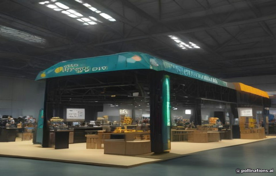
Winning a robotic case packer demo at PACK EXPO International requires prototypes whose ECT (per TAPPI T811), BCT (per ASTM D642), and dimensional tolerances (±0.5mm on flaps and slots) match the production spec exactly — which demands a digital CAD-to-digital-cutting workflow, not a conventional tooling cycle. TadaPack delivers zero-tooling-fee, fully printed 24-48 hour prototypes validated against ISTA 3A handling sequences, so exhibitors can demo robot compatibility and transport survivability before booth setup.
Why Robotic Case Packer Demos Punish Non-Production-Grade Prototypes
Robotic palletizing and case packing demos at PACK EXPO International have become the single highest-stakes procurement theater on the show floor, and 2026 shows are dominated by vacuum-end-effector and form-fit-function machines that assume your case lands within a ±3mm envelope of its dieline specification. A prototype cut on tolerance-drifted equipment — flap length variance beyond ±1.5mm, slot depth off by 1mm, or caliper deviation exceeding ±0.15mm — will mis-feed, skew in the magazine, or collapse under vacuum pickup, and the brand owner watching the demo draws the wrong conclusion about the robot when the real root cause is the box.
This is why the 24-48 hour prototype window matters so much: it is not about speed for its own sake, it is about closing the loop between the structural CAD file, the robot OEM’s gripper spec sheet, and a physically measurable sample before the demo slot. Conventional sampling with rotary die tooling typically runs 8-12 business days and costs $500-$2,000 in tooling per size; a digital die-cut workflow with no physical tool eliminates both the wait and the fee, which is the entire economic basis of zero-tooling-fee sampling for exhibition-grade samples.
The Physics Stack: ECT, McKee BCT, and Robotic Vacuum Pickup
Robot demo failure modes trace back to three material mechanics properties. First, board compression: the McKee formula (BCT ≈ 5.87 × ECT × √(caliper × perimeter)) predicts box compression from edge crush and caliper, and it governs whether the case survives the vacuum head’s downward clamping force of typically 0.3-0.8 bar applied across the top panel. Second, flexural stiffness: E-flute (1.5mm caliper) and B-flute (3.0mm caliper) behave very differently under point vacuum suction — a 90mm vacuum cup on thin E-flute can dimple the top panel enough to trigger the robot’s Z-axis over-travel fault. Third, coefficient of friction: uncoated kraft versus UV-coated display-grade liners can vary the liner-to-magazine friction coefficient by 0.15-0.30, which changes singulation reliability.
Q: If the McKee formula derives BCT from ECT and caliper, why do US enterprise POs still mandate Mullen burst testing per TAPPI T 810?
A: Because Mullen (burst, e.g., 200 lb/in² on 275# board) captures out-of-plane fiber bond strength and liner delamination risk that ECT alone does not — ECT measures column crush in one direction while burst measures the lamination integrity of the liner-to-medium bond. Per TAPPI Standard T 810, Mullen burst of 200 lb/in² remains the legacy procurement gate for parcel-network shipping, even though McKee-based ECT specification is more predictive of stacking. Practical recommendation: specify ECT for warehouse stacking and robot clamping, retain Mullen only where legacy customer contracts or carrier-class packaging rules demand it.
Materials & Construction Matrix for Demo-Grade Prototypes
| Application | Spec | Key Engineering Parameter | Governing Standard / Test Protocol |
|---|---|---|---|
| Robot demo shipper case | C-flute, ECT-32/ECT-44, 175gsm kraft liner | BCT ≥ 250 lbf design load; flap tolerance ±0.5mm | ASTM D642 / TAPPI T 811 |
| Booth sample shipper (fragile display units) | BC double-wall, molded pulp or EPE dunnage | Drop shock: 10 drops, ≤ 46 in drop height seq. | ISTA 3A General Simulation |
| VIP retail gift box (short-run, zero plate fee) | 350gsm CCNB over E-flute, soft-touch laminate, PFAS-free barrier | Cobb 60 ≤ 35 g/m²; caliper ±0.15mm | ISO 535 / ISO 186:2020 |
| Sustainability compliance claim | Recyclable mono-material corrugated | Weight of recyclable fraction vs PPWR thresholds | EU PPWR (Reg. 2025/40) / EU 94/62/EC Annex II |
| Distribution cycle verification | Full distribution simulation, air + truck legs | Random vibration: 0.52 Grms PSD profile | ASTM D4169 DC-13 |
Two 2026-relevant compliance notes. Under EU PPWR (Regulation 2025/40, replacing the operational provisions of Directive 94/62/EC), all packaging placed on the EU market must be recyclability-graded by design-for-recycling criteria with phase-in milestones running through the 2030s — mono-material corrugated with PFAS-free barrier coatings is the safest demonstrable position at a US show with European sourcing teams present. And per FTC Green Guides (16 CFR Part 260), any ‘recyclable’ claim printed on booth packaging must be substantiated by the accessible recycling share of the destination market, so avoid unqualified claims on samples headed to multi-region visitors.
24-48H Rapid Prototyping SOP: CAD to Robot-Ready Sample
The compressed timeline only works if every step has a hard tolerance gate. The following is the standard TadaPack SOP for exhibition-grade samples:
Step 1 — Structural CAD lock (Hour 0-4). Import or build the dieline in CAD with verified 3D fold simulation; confirm slot depth = material caliper + 0.3mm, and lock all flap tolerances to ±0.5mm. Validate stacking math using the free calculators at tadapack.com/tools (BCT estimate from ECT and caliper, container utilization, dimensional-weight exposure per FBA rules).
Step 2 — Digital die layout & imposition (Hour 4-8). Nest the dieline on the press sheet with ±0.15mm registration allowance; specify crease matrix by durometer (a 45-durometer creasing matrix on E-flute, 0.5mm crease rule on B/C-flute) so fold lines land inside ±0.3mm of the CAD origin — this is the single most common source of robotic skew in prototypes.
Step 3 — Digital print & finishing (Hour 8-24). Run digital CMYK or HP Indigo-class toner/inkjet output on the production-intended substrate (never substitute a lighter board for the demo — the substitution itself invalidates the robot test); apply PFAS-free barrier coating if Cobb 60 performance matters for the return journey. Conditioning: 24 hours at 23°C ± 1°C, 50% ± 2% RH per ISO 187:2020 before any compression test, or you are testing a moisture-skewed board.
Step 4 — Verification gate (Hour 24-48). Measure caliper (TAPPI T 411 digital micrometer, ±0.15mm tolerance), confirm ECT on a test coupon, run a single-drop pre-check on the packed sample, and record a signed dimensional report shipped alongside the case so the integrator can pre-program the robot gripper to your actual — not nominal — geometry.
Freight Survival: Getting Fragile Demo Units to the Booth Intact
Prototypes that fail in transit never get their demo. Per ISTA 3A General Simulation Performance Testing, packaged products up to 150 lb face atmospheric conditioning, shock (drop sequences up to the applicable height), and random vibration profiles that simulate parcel networks — for exhibition samples crossing the Pacific or Atlantic, ocean-leg humidity is the hidden failure driver. Container sweat and 30-day transit humidity can drive corrugated moisture content from a nominal 7-8% to 13-14%, dropping effective ECT by 20-30% and softening flute walls; Cobb 60 water absorption above 35 g/m² on the liner signals delamination and edge-pulp blowout risk, so specify water-resistant coatings or wax-alternative barriers on any case that spends time in a container.
Regional stack derating also matters for exhibitors shipping demo stock into distribution hubs. High-humidity coastal gateways (Port of Rotterdam’s multimodal rail/road network, and US West Coast ports feeding the California Inland Empire — ONT8/LGB3 FBA catchment) warrant a 15-25% BCT derating factor versus dry inland conditions; the Texas DFW triangle sits in a mixed-humidity zone where a 10-15% derate is typical engineering practice. Where FBA dimensional-weight penalties apply, remember 2026 dimensional rules charge on volume divisor (139 in³/lb standard), so a demo case that is structurally oversized is paying freight on air — run the dimensional exposure calc at tadapack.com/tools before committing to a case size.
Troubleshooting matrix (hypothetical failure scenarios):
- Flap popping / panel bowing in the robot magazine: root cause is crease-matrix durometer mismatch or excessive slot depth (slot > caliper + 0.5mm); corrective action is re-cutting with a 45-durometer matrix on E-flute and verifying slot depth on a first-article sample.
- Top-panel dimpling under vacuum pickup: root cause is caliper insufficiency for the cup footprint; corrective action is stepping from E-flute to B-flute, or adding a 20% internal top-panel void support, and re-derating the vacuum pressure in the gripper program.
- Grayboard/CCNB warping after ocean transit: root cause is asymmetric moisture uptake through an uncoated outer liner; corrective action is balanced coating both faces and sealing case edges with moisture-barrier tape, then re-verifying Cobb 60 ≤ 35 g/m².
- Adhesive debonding at glued corners under humidity: root cause is cold-temperature adhesive set during winter ocean legs; corrective action is specifying a low-temperature-set hot-melt rated to at least 0°C application cure.
Cost & Procurement Benchmark: Zero Tooling vs Conventional Sampling
For a hypothetical worked example (not a quotation): a three-SKU prototype set for a PACK EXPO robot demo — one C-flute ECT-32 shipper, one BC double-wall fragile-sample shipper with molded pulp, and one 350gsm CCNB-over-E-flute VIP box with soft-touch finish — would typically carry $1,500-$4,500 in conventional rotary tooling and 8-12 business days lead time. Under a digital zero-tooling workflow, tooling cost is $0 and lead time compresses to 24-48 hours per set, with unit prototype cost typically 2-3× the eventual mass-production unit cost — a premium that is trivially justified when the demo slot itself represents a six-figure OEM evaluation. Procurement directors should also price the failure alternative: a mis-feed at the integrator demo typically resets the evaluation cycle by one quarter.
For exhibitors and sourcing teams preparing for PACK EXPO International, TadaPack’s structural engineering desk provides CAD prototype development, substrate selection (ECT burst-mapped across E/B/C/BC flutes), PFAS-free barrier options compliant with EU PPWR recyclability grading, and free online calculators for BCT, dimensional weight, and container utilization at tadapack.com/tools.
Recommended Engineering Reading
[TOOLS] Featured Engineering & Calculation Tools
Explore 70+ Packaging Tools ➔Box Compression (BCT) Calculator
Predict box compressive limit and stacking safety factors via McKee formula.Edge Crush Test (ECT) Calculator
Calculate linerboard ring crush and composite ECT ratings for optimal board specs.
