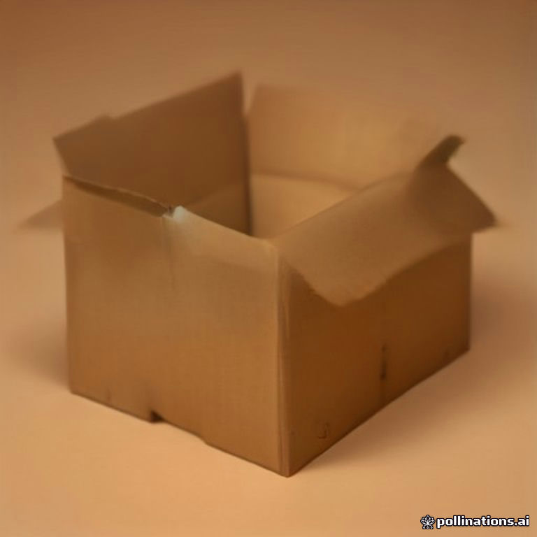
A packaging prototype generator converts CAD dielines into physical or digital validation samples—typically E/B/C-flute corrugated or 350gsm CCNB rigid structures—before tooling commitment. Structural sign-off requires conditioning per ISO 186:2020 (23°C ±1°C, 50% ±2% RH) followed by ASTM D642 compression and ISTA 3A transit simulation to confirm the prototype’s BCT meets stacking derated loads.
E-commerce brands shipping through Amazon FBA now face dimensional-weight penalties that make prototyping errors unbearably expensive: a single 6mm overage in box depth can push a SKU into the next billing tier. That cost pressure is why digital packaging prototype generators—CAD-driven platforms that output press-ready dielines and virtual mockups in hours rather than weeks—have become a procurement-stage necessity. This whitepaper dissects the mechanics, tolerance stack-ups, validation protocols, and cost matrix behind professional prototype generation, anchored to TadaPack’s custom structural prototyping service and free calculation tools (https://tadapack.com/tools).

1. What a Packaging Prototype Generator Actually Does: The Engineering Pipeline
A professional prototype generator is not a template library. It is a parametric CAD pipeline with four stages: (1) internal dimension input (L × W × D plus product mass and fragility factor), (2) automated dieline generation with flute-corrected scoring allowances, (3) material assignment with ECT/burst lookup, and (4) export to vector cutting formats (DXF/PLT) for flatbed or digital knife cutting of a one-off sample.
The generator’s value is in flute-corrected scoring: a 90° fold on C-flute requires a 2.0–2.5mm crease rule offset because the fluted medium compresses asymmetrically. Generic template tools ignore this, which is why generator-produced samples from template engines fail ISTA drop testing at the flap corners.
Q: If the McKee formula derives BCT directly from ECT and perimeter, why do enterprise POs still mandate physical Mullen burst testing on prototype samples?
A: Direct answer: because McKee (BCT ≈ 5.87 × ECT × √(perimeter × caliper)) is a statistical regression with ±10–15% scatter, while burst testing per TAPPI T810 (2026 Revision) provides independent fiber-bond verification. Mechanical reason: corrugated board can satisfy ECT through flute geometry alone while exhibiting low interlaminar bond strength—exactly the failure mode that delaminates under ocean-humidity cycling. Procurement recommendation: accept McKee for preliminary stacking calculations, but contractually require TAPPI T810 burst (typically 200–275 kPa for 32 ECT C-flute) and Cobb 60 absorption on the prototype substrate lot before tooling release.
2. Material Selection Matrix: Flute, Caliper, and Board Grade
Prototype fidelity depends on matching the sample substrate to the production substrate. Cutting a prototype from 200gsm kraft when production runs 350gsm CCNB invalidates every subsequent compression result. The matrix below reflects 2026 North American and EU procurement benchmarks for the most common prototype-to-production pairings.
| Structure | Typical Caliper | Strength Class | Primary Application | Governing Standard / Test Protocol |
|---|---|---|---|---|
| E-flute corrugated | 1.5 mm | ECT-29 to ECT-32 | DTC mailers, printed retail cartons | TAPPI T810 (2026 Revision) / ASTM D642 |
| B-flute corrugated | 3.0 mm | ECT-40 (dual 44 available) | Die-cut inserts, cushioning trays | ASTM D4169 Distribution Cycle DC-13 |
| C-flute corrugated | 4.0 mm | ECT-32 / ECT-44 | Master shipper cases | TAPPI T810 (2026 Revision) / ISTA 3A |
| BC double-wall | 7.0 mm | ECT-48+ | Heavy pallet loads, ocean export | ASTM D642 / ISO 2247 vibration |
| 350gsm CCNB rigid | 0.45–0.50 mm per ply | N/A (rigid wrap) | Luxury rigid boxes, setup boxes | ISO 186:2020 conditioning / Cobb 60 |
All substrates must be conditioned per ISO 186:2020 specifications (23°C ± 1°C, 50% ± 2% RH) for a minimum of 24 hours before any physical prototype testing; testing unconditioned blanks can inflate ECT readings by up to 8% in dry winter warehouse air, producing falsely optimistic validation data.
3. Validation Protocol: The 4-Step Prototype Verification SOP
Once the generator outputs a physical sample, run this SOP before releasing tooling POs:
Step 1 — Dimensional audit (±0.15mm tolerance). Measure internal dimensions with a calibrated digital caliper per TAPPI T411; internal L × W × D must fall within ±0.15mm of the CAD nominal for folding cartons and ±0.5mm for corrugated (flute springback allowance). Reject any blank with score registration drift beyond ±0.15mm.
Step 2 — Compression verification. Test five conditioned samples in strict accordance with ASTM D642 (Standard Test Method for Determining Compressive Resistance of Shipping Containers). Mean BCT must exceed the derated stacking load with a safety factor of 3.5 for warehouse stacking up to 8 weeks (per ASTM D4169 Clause guidance); a hypothetical worked example: a 12 kg case stacked 5-high with a 4-week dwell needs BCT ≥ 5 × 12 kg × 9.81 / 1 × 3.5 ≈ 1.7 kN at minimum.
Step 3 — Transit simulation. Run ISTA 3A General Simulation Performance Testing for single-parcel distribution: drop shock sequences up to the height specified for the packaged mass, followed by random vibration at the 3A spectrum. Any flap gap opening >1.5mm or corner crush >5mm constitutes failure.
Step 4 — Humidity resilience check. Expose a second sample set to 90% RH for 48 hours, then re-run ASTM D642 compression. BCT retention below 70% indicates inadequate liner grade or an unsealed adhesive system—return to the generator and upspec the liner or specify a PFAS-free water-resistant barrier coating.
4. Defect Diagnostics: Troubleshooting Prototype Failures
Flap popping on E-flute samples. Root cause: creasing matrix durometer below specification or crease-channel width mismatched to caliper. Corrective action: switch to a 45-durometer creasing matrix with channel width = caliper + 0.3mm (1.8mm channel for 1.5mm E-flute) and verify creasing rule height against a ±0.1mm make-ready gauge.
Grayboard warping on rigid box prototypes (V-groove wrap). Root cause: moisture gradient across the grayboard ply during wrap lamination—differential hygroexpansion bows the panel. Corrective action: pre-condition grayboard and 128gsm wrap paper to ISO 186:2020 equilibrium, apply adhesive at 30–40 g/m² wet coat with full-coverage roller, and clamp under 0.2 MPa pressure for 90 seconds. For EU-bound shipments, also verify Cobb 60 absorption stays below 35 g/m²; exceeding this threshold triggers transit delamination of the wrap layer during Atlantic crossings.
Adhesive debonding under ocean humidity. Root cause: low-solids PVA adhesives re-emulsify above 85% RH over multi-week dwell. Corrective action: specify a crosslinking (water-resistant) PVA or hot-melt system and validate with a 7-day 40°C / 90% RH climate chamber cycle before containerization.
5. Freight Corridor Stress Analysis & Landing Hub Considerations
Prototype validation must anticipate the actual distribution corridor. Pacific routes into the California Inland Empire (FBA ONT8 / LGB3 nodes) impose 25–35 day container dwells where container sweat can drive chamber RH above 80%, softening C-flute by effectively derating stacking performance 15–20% versus lab-dry conditions. The Texas DFW distribution triangle sees wider thermal swings; corrugated becomes brittle below 0°C and loses compression above 35°C, so double-wall BC with ECT-48 is the engineering default for high-value cross-dock loads. Rotterdam multimodal rail/road connections subject prototypes to ISO 2247 vertical repetitive shock during rail humping—warping inserts and unbraced inner cartons are the dominant failure modes on European DC-bound shipments.
Stacking derating for high-humidity coastal ports should apply a 1.3–1.5 load factor versus inland dry-warehouse assumptions. TadaPack’s free calculator suite (https://tadapack.com/tools) lets you input your corridor, stack height, and dwell time to interactively verify derated BCT requirements against your generator’s ECT output—use it before every tooling release.
6. Cost Matrix: Prototype Generation vs. Error Cost
A digital prototype run in 2026 typically costs $50–$250 for a single physical sample via digital knife cutting (no die cost), versus $800–$2,500 for a production die-cut sample run, versus $15,000–$60,000 for full tooling on a rigid box line. Under EU Directive 94/62/EC Annex II and the EU PPWR (Regulation 2024/1991) packaging waste reduction mandates, prototypes must also validate recyclability—mono-material structures and PFAS-free barrier coatings should be locked at the prototype stage, because redesign after tooling invalidates the entire cost advantage. Per FTC Green Guides (16 CFR Part 260) substantiation rules, any recyclability claim carried into US marketing must be verified against the actual prototype substrate composition, not the generator’s default material assumption.
Procurement rule of thumb: budget 1–2% of projected annual packaging spend for prototype validation. Skipping it to compress launch schedules routinely converts a $150 prototype decision into a full tooling rework order.
For structural prototyping with flute-corrected dielines, production-matched substrates, and ISO-conditioned validation sampling, request a quote through TadaPack’s custom structural packaging service (https://tadapack.com), and run your stacking and dimensional-weight scenarios through the TadaPack calculation tools before committing to tooling.
Recommended Engineering Reading
[TOOLS] Featured Engineering & Calculation Tools
Explore 70+ Packaging Tools ➔Box Compression (BCT) Calculator
Predict box compressive limit and stacking safety factors via McKee formula.Edge Crush Test (ECT) Calculator
Calculate linerboard ring crush and composite ECT ratings for optimal board specs.
