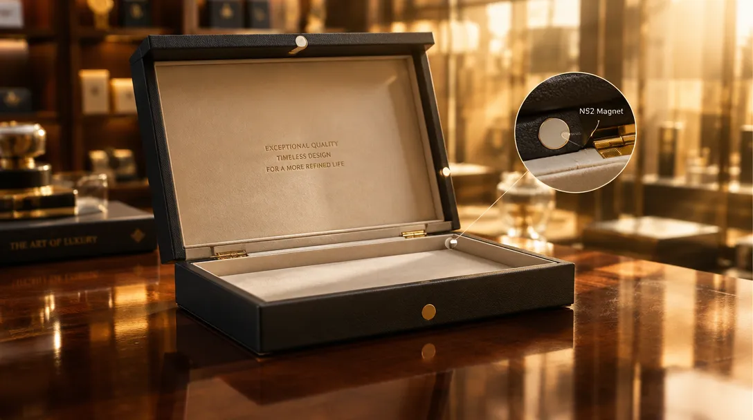
For custom magnetic closure gift boxes, specify grayboard hinge thickness of 1.5–2.5 mm with a 0.8–1.2 mm crease radius to achieve ≥10,000 open-close cycles before delamination, and size N52 magnets to deliver 300–600 g pull force per closure point so the lid resists ISTA 3A drop-shock separation. Use the step-by-step SOP below to lock hinge geometry, magnet placement, and fatigue validation before tooling release.
Premium DTC gift packaging has shifted toward heavier rigid structures in 2026, driven by EU PPWR recyclability mandates and rising Amazon FBA damage claims — but the two failure modes that kill a magnetic closure box in the field are mechanical, not aesthetic: hinge fatigue delamination and insufficient magnetic retention. This guide gives procurement teams a repeatable engineering procedure to specify and validate both.

1. What You Need Before Specifying: Materials, Tools & Reference Standards
Gather the following before any drawing is issued to the die-maker:
- Grayboard stock: 1.5–2.5 mm (approx. 36–60 pt) recycled grayboard for the base and lid walls; verify caliper per TAPPI T411 (±0.15 mm typical production variance).
- Wrap substrate: 120–157 gsm art paper or specialty wrap; heavier wraps add stiffness that increases hinge moment.
- N52 neodymium magnets: disc or block, typically 10×2 mm to 20×3 mm, nickel-plated, recess-mounted in grayboard pockets.
- Adhesive: hot-melt or animal glue rated for ≥ -20°C; check bond integrity under humidity per Cobb 60 absorption limits on the wrap stock (≤35 g/m² typical spec ceiling to avoid crease-zone softening).
- Test references: ASTM D4169 (distribution cycle), ISTA 3A (e-commerce parcel simulation), ISO 187 conditioning, TAPPI T411 (caliper).
- Force gauge (digital push-pull, 0–2 kg range, ±1% accuracy) and a manual cycle rig or robotic arm for fatigue runs.
2. Step-by-Step: Sizing the Hinge for Fatigue Life
The hinge in a book-style or flip-top magnetic box is an integral wrapped crease, not a mechanical hinge — its life depends on grayboard thickness, crease radius, and wrap grain direction. Follow this ordered SOP:
- Set hinge grayboard thickness. Key point: thicker board survives more cycles but needs a wider crease. Use 1.5 mm for lids under 150 mm span, 2.0–2.5 mm above 250 mm span. Tolerance: caliper ±0.15 mm per TAPPI T411.
- Define crease radius and depth. Key point: the crease must score through roughly 50–60% of board thickness so fibers fold rather than fracture. Target radius 0.8–1.2 mm. Tolerance: ±0.1 mm on rule depth; misregistration beyond ±0.15 mm shifts the neutral axis and cuts cycle life sharply.
- Orient wrap grain parallel to the hinge axis. Key point: cross-grain wrap on the crease zone is the #1 cause of early delamination because paper tears along the fiber direction under repeated flex. Tolerance: grain direction must be within ±5° of hinge axis.
- Set adhesive application. Key point: full-surface glue coverage across the hinge inner wrap, 20–30 g/m² hot-melt; skip-lines at the crease concentrate stress. Tolerance: coverage uniformity ±10%; no dry spots within 5 mm of the crease line.
- Prototype and cycle-test. Key point: run 10,000 open-close cycles at ~1 Hz in a conditioned room (23°C, 50% RH per ISO 187). Pass criterion: no visible delamination >10% of hinge length and no wrap cracking. Tolerance: cycle count ±5% repeatability across three samples.
Q: Why not just use thicker board everywhere to extend hinge life?
A: Direct answer — beyond ~2.5 mm, cycle life gains flatten while lid-closing force needed to seat the magnets rises steeply. Underlying mechanics — flexural moment at the crease scales with the square of thickness, so doubling board thickness quadruples the moment the wrap must absorb per cycle, accelerating fiber fatigue even as delamination resistance improves. Procurement recommendation — optimize crease radius and grain orientation first; only increase thickness when lid span exceeds ~250 mm, and confirm magnet pull force rises proportionally (see Section 3).
3. Step-by-Step: N52 Magnet Sizing & Placement
N52 is the highest energy-product grade of sintered neodymium commonly stocked; the goal is enough pull force to hold the lid closed through parcel drop and vibration, without making the box hard to open for the end user (target lid-open effort roughly 500–1,500 g at the leading edge for adult premium products).
- Calculate required pull force per closure point. Key point: as a hypothetical worked example, a 300×220×80 mm book-style box with ~600 g lid-plus-contents effective mass needs 2× N52 magnets each delivering 300 g direct pull (600 g total) to prevent lid separation in a 1 m drop per ISTA 3A sequences. Tolerance: magnet pull-force spec ±10% measured with the magnet recessed at final depth.
- Select magnet geometry. Key point: pull force scales roughly with face area and drops sharply with air gap — a 15×3 mm N52 disc at 0 mm gap may deliver ~1.5 kg, but each 0.5 mm of grayboard/skive gap can halve it. Specify recess depth so magnet face sits ≤0.3 mm below the wrap surface. Tolerance: recess depth ±0.2 mm.
- Set pole orientation and pairing. Key point: opposite poles facing across the lid/base gap maximize attraction; ensure both magnets in a pair are N52 with matched magnetization direction — mixed grades create asymmetric closing feel. Tolerance: pull-force mismatch between paired magnets ≤15%.
- Mount and validate against transit shock. Key point: after assembly, run ASTM D4169 or ISTA 3A drop and vibration sequences; pass criterion is lid remains closed (no magnet separation) through the full sequence with no magnet pocket cracking. Tolerance: no more than 1 mm lid displacement post-test; zero detached magnets.
| Parameter | Typical Spec Range | Governing Standard / Test Protocol |
|---|---|---|
| Hinge grayboard caliper | 1.5–2.5 mm (±0.15 mm) | TAPPI T411 |
| Crease radius | 0.8–1.2 mm (±0.1 mm) | Internal die-spec practice |
| Hinge fatigue pass criterion | ≥10,000 cycles, ≤10% delamination | ISO 187 conditioning (23°C, 50% RH) |
| Magnet pull force per point | 300–600 g (±10%) | Digital force gauge, ±1% accuracy |
| Transit retention | Lid stays closed; ≤1 mm displacement | ASTM D4169 / ISTA 3A |
| Wrap moisture ceiling | Cobb 60 ≤35 g/m² | ISO 535 / Cobb 60 |
4. How to Check the Result: Verification Checklist
Before releasing mass production, tick every line below on a pilot sample set (minimum 3 units, conditioned per ISO 187):
- ☐ Hinge survives 10,000 open-close cycles with delamination ≤10% of hinge length.
- ☐ Crease radius measured at 0.8–1.2 mm on a cross-section cut.
- ☐ Wrap grain axis within ±5° of hinge axis on all four hinge panels.
- ☐ Each magnet pair measures 300–600 g combined pull at the closed seam (±10%).
- ☐ Magnet recess depth ≤0.3 mm below wrap surface; no adhesive bleed into the gap.
- ☐ ASTM D4169 / ISTA 3A drop sequence completed with lid closed throughout.
- ☐ No grayboard warping >2 mm across any panel after 48 h at 50% RH.
- ☐ Recyclability declaration documented per EU PPWR (Regulation (EU) 2024/1991) material composition requirements.
5. Common Mistakes & Defect Troubleshooting
Two recurring field defects dominate warranty claims on magnetic closure boxes:
Defect 1 — Early hinge delamination (<1,000 cycles). Root causes: cross-grain wrap orientation at the crease; score depth below 40% of board thickness, forcing fiber fracture instead of fold; adhesive skip-lines within 5 mm of the crease. Floor-level corrective actions: re-orient wrap sheets so machine direction runs along the hinge; deepen creasing matrix by 0.1 mm increments and re-cycle 3 samples each step; switch to a full-transfer hot-melt and verify 20–30 g/m² coat weight on the hinge zone.
Defect 2 — Lid pops open during transit (magnet separation). Root causes: pull force sized at 0 mm air gap while the production build leaves 0.5–1.0 mm of grayboard and skive in the gap; magnets glued at wrong polarity after manual assembly; magnet pockets cracked by drop shock because recess walls are thinner than 1.5 mm of board remaining. Corrective actions: re-specify pull force measured in the as-built recessed state, not the bare-magnet datasheet value; add polarity-check jigs at assembly; increase pocket wall minimum to 1.5 mm grayboard or line the pocket with a rigid liner. Humidity note: ocean-freight container sweat can soften the crease zone if wrap Cobb 60 exceeds spec — dehumidified container loading or desiccant strips are the standard countermeasure for Pacific and Atlantic lanes.
6. Procurement Workflow & TadaPack Validation Support
Lock these decisions in this sequence to avoid retooling: (1) finalize hinge geometry and crease spec on a CAD prototype, (2) confirm magnet pull force on the pilot build with a force gauge, (3) run the transit-simulation validation, then (4) release tooling. TadaPack’s structural prototyping service produces short-run pilot magnetic closure boxes with specified N52 magnet recesses and crease tooling so you can execute the SOP above before committing to wholesale MOQ volumes; the free calculators at tadapack.com/tools help you size board caliper and freight dimensions (including FBA dimensional-weight exposure) interactively. For quotes and DFM review, start at tadapack.com.
Recommended Engineering Reading
[TOOLS] Featured Engineering & Calculation Tools
Explore 70+ Packaging Tools ➔Box Compression (BCT) Calculator
Predict box compressive limit and stacking safety factors via McKee formula.Edge Crush Test (ECT) Calculator
Calculate linerboard ring crush and composite ECT ratings for optimal board specs.
